Loss Testing with a Power Meter & Light Source
With high-speed internet being such a necessity now in so many households, the importance of maintaining fiber optic infrastructure has never been more important. A huge part of preserving that integrity is having the right testing equipment for testing network loss. Fiber optic loss testing is an essential part of maintaining reliable, high-performance fiber optic networks because it helps identify potential issues and ensures that the system meets the required performance specifications. In this blog, we’ll explore what a power meter and light source are and provide a simple, step-by-step guide on how to perform loss testing accurately.
What Are a Power Meter and Light Source?

A power meter and light source are essential test tools that work in tandem to measure fiber optic cable loss and evaluate the quality of optical links. They provide the data necessary to quantify signal loss and pinpoint issues that could impact network performance. Here's how they work:
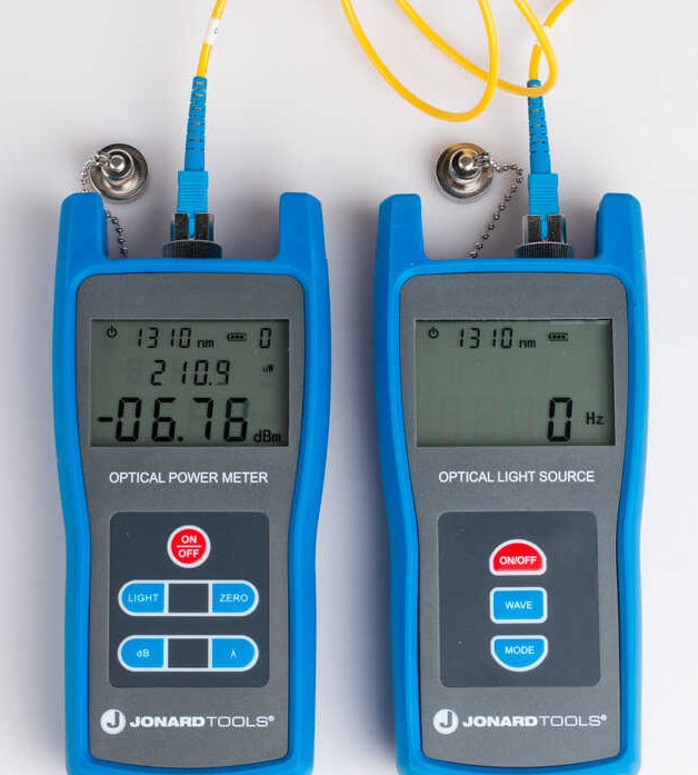
A power meter measures the optical power level of light received at the end of a fiber link. This device is crucial for determining how much light has successfully traveled through the fiber and how much has been lost during transmission. Results from a power meter are displayed in either decibels (dB), which indicate relative loss compared to a reference level, or decibel-milliwatts (dBm), which show the absolute power level relative to one milliwatt. Modern power meters are designed to operate across a wide range of wavelengths, such as 850 nm, 1300 nm, 1310 nm, and 1550 nm, ensuring compatibility with various fiber types. Their high sensitivity allows them to detect minute changes in light power, providing precise and reliable measurements for both installation and maintenance tasks.
The light source, on the other hand, emits a stable and consistent optical signal at a specified wavelength, which is injected into the fiber under test. It serves as the "input" for the fiber link, establishing a baseline power level that the power meter uses to measure loss. Light sources are calibrated to operate at standard wavelengths depending on the type of fiber being tested. For multimode fibers, common wavelengths are 850 nm and 1300 nm, while single-mode fibers typically operate at 1310 nm and 1550 nm. The stability of the light source ensures consistent output, minimizing any fluctuations that could affect test accuracy.
When used together, the power meter and light source enable a step-by-step process for assessing fiber optic link performance. First, the light source emits a controlled signal into one end of the fiber. As the light travels through the link, it may encounter various forms of attenuation, such as dirty connectors, poor splices, or bends in the fiber. At the other end of the fiber, the power meter measures the light intensity received. By comparing the measured power level to the initial reference power level established by the light source, the total loss can be calculated in decibels.
Step-by-Step Guide: How to Perform Loss Testing with a Power Meter and Light Source
With that being said, here’s a simple guide to performing loss testing with a power meter and light source.
Step 1: Prepare for Testing
The first, and arguably most important step, is to clean the connectors - dirt and dust on fiber connectors can significantly affect test results. Begin by thoroughly cleaning the connectors on both ends of the fiber link with lint-free wipes and isopropyl alcohol. You can use a fiber optic inspection microscope to help verify that the connectors are completely clean.
Next, it's important to select the appropriate wavelength. Make sure you choose the wavelength that matches the operating wavelength of the fiber system you’re testing. For multimode fiber, typically use 850 nm or 1300 nm; for single-mode fiber, use 1310 nm or 1550 nm.
Step 2: Establish the Reference Power Level
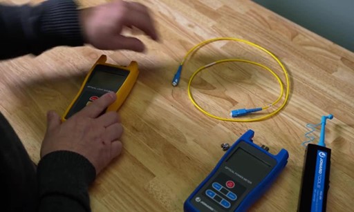
Now it's time to connect the light source to the power meter by using a short, high-quality reference cable. This step ensures minimal or no loss, establishing a baseline measurement. Once the baseline measurement has been established, power on both the light source and power meter, allowing a few seconds for stabilization. With the reference cable connected, read the power level on the power meter. Use the power meter's “Set Reference” function (if available) to establish the baseline power level as 0 dB or note the initial reading as your reference.
Step 3: Test the Fiber Link
Next, it's time to connect the light source to one end of the fiber link. Disconnect the light source from the reference cable and attach it to one end of the fiber link you want to test. Make sure that you secure the connection to avoid any disconnection during testing. Afterwards, connect the power meter to the other end of the fiber link by attaching it to the opposite end of the fiber link. Make sure it’s secure and check that the connectors are still clean.
Finally, it's time to take the measurement. Turn on the light source, and the power meter will measure the amount of light that reaches the other end of the fiber. The power meter will display the measured power level, showing how much light has been lost from the light source to the power meter.
Step 4: Calculate the Loss
Using the reference power level, it's time to calculate loss! Subtract the measured power reading from the initial reference power level (set in Step 2). The result is the total loss across the fiber link, typically displayed in decibels (dB). Using this, you want to compare the calculated loss to the acceptable loss standards for your fiber optic network. The acceptable loss can vary depending on fiber type, network length, and specific application requirements, but in general, single-mode fibers allow 0.4 dB per kilometer at 1310 nm and 0.3 dB per kilometer at 1550 nm, while multimode fibers allow about 3.0 dB per kilometer at 850 nm and 1.5 dB at 1300 nm.
Step 5: Document Results
Document the results for future reference and record-keeping. Note the measured loss, reference power level, wavelength used, and any relevant observations. Documentation is critical for ongoing maintenance, future troubleshooting, and verifying that the system is functioning within acceptable limits.
Step 6: Troubleshoot If Necessary
If the loss exceeds acceptable limits, further investigation is required to identify the source of the issue. Possible causes of high loss include dirty connectors, damaged fiber, poor splices, or incorrect connector mating. Use a fiber optic inspection scope to check connectors, and consider additional OTDR testing to locate faults along the fiber length.
Conclusion

Fiber optic loss testing with a power meter and light source is essential for maintaining optimal network performance and diagnosing issues before they cause significant disruptions. By following these steps, you can accurately measure the total loss in a fiber optic link and ensure it falls within acceptable standards. Proper testing helps maintain signal quality, minimizes downtime, and extends the life of fiber optic installations. A well-executed loss test not only confirms that the fiber link is ready for operation but also provides valuable baseline data for future maintenance and troubleshooting.

Comments
Login or Register to post comments.