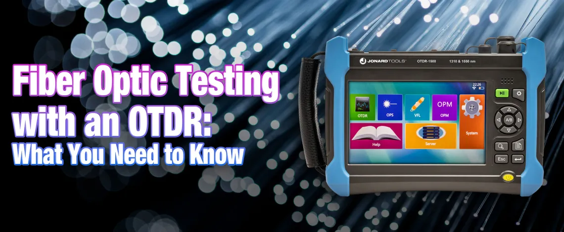
Fiber Optic Testing with OTDRs: What You Need to Know
Introduction
An Optical Time Domain Reflectometer (OTDR) is a valuable fiber optic testing device used for accessing network construction, identifying fiber break points, measuring cable lengths, and calculating relative optical power losses. Fiber Optic Testing with OTDRs function by sending a short pulse of light into the fiber and measuring the amount of light that is reflected back. In turn, the amount of reflected light is used to determine the location and severity of potential faults in the fiber. One of the most useful features of the OTDR is that it creates a graphical image identifying faults in the fiber optic cable. Understanding how to read and interpret these graphs are of utmost importance: in fact, it is reported that contractors lose as much as $100,000 in materials due to improper interpretation of OTDR test results. Luckily, a lot of OTDRs offer built-in event mapping, allowing for an easy visual representation. Without further ado, let’s dive into some of the unique features that make the OTDR an invaluable piece of testing equipment for Fiber Optic Technicians.
OTDR Module
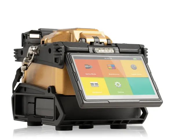
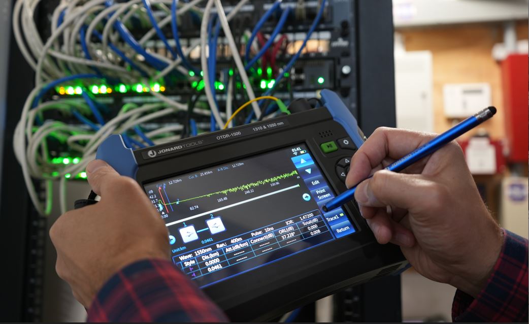
The first, and perhaps most important module included in an OTDR is the OTDR module! Before proceeding with this module, it's important to check adapter compatibility - for instance, our OTDR-1500 is only compatible with APC adapters, which come in the package. Furthermore, you must have a launch cable to connect to. They serve as an extension of the optical path, allowing the OTDR to capture reflections and measurements accurately by eliminating the effects of dead zones.
As previously mentioned, the OTDR works by sending and receiving a small pulse of light, which it uses to determine the severity and location of the fault. The fault is then represented in a graphical illustration- in contrast to our older model, our OTDR-1500 actually includes a touchscreen feature for easy maneuverability.
Due to the abundance of data presented, using the OTDR module can feel overwhelming. Luckily, though, most devices offer easy-to-follow instructions that can make using it much easier. To begin using the OTDR module, first you must set your test parameters. Once you click the device's “test conditions” button, you will usually have the option to test on 1310nm and 1550nm wavelengths. One of the unique features of our OTDR is that it allows you to view the results of two wavelengths at the same time. Depending on the fault you’re looking for, having both wavelengths available can be helpful because some faults are more likely to be detected under certain wavelengths.
Before connecting the fiber cable to the OTDR, make sure you've established the specifications of the fiber in the OTDR settings. Additionally, always make sure the connectors are cleaned properly. Once you’ve established your parameters, it’s time to connect the test fiber to the OTDR optical input port! You want to make sure the test fiber is not live before connecting. To test, just press the "play" button on the OTDR so that your OTDR can display the test curve and mark the events accordingly. Below is an illustration of what it might look like:
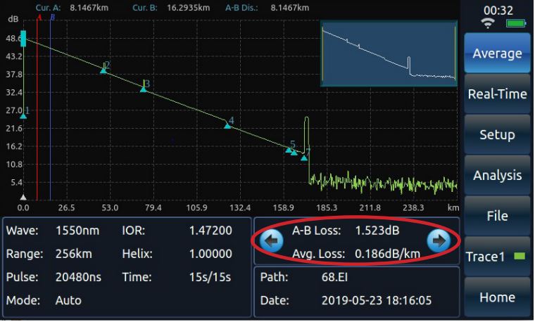
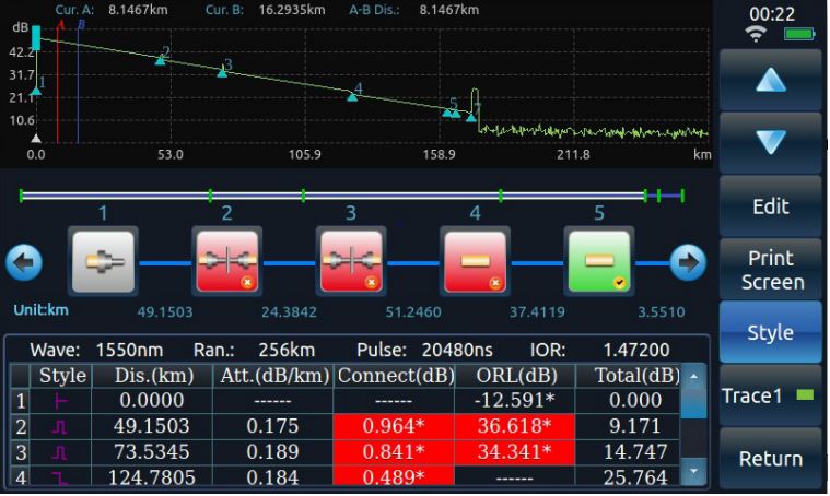
By moving through the arrows circled above, the OTDR can show you statistics such as average loss, connection loss, and reflection loss, amongst other things. After running the test, you can also view the event list in order to get a better understanding of the problems being detected. In order to display the event map, there should be an “analyze” button somewhere on the screen that will allow you access to the results. This will show you the list of events occurring in the fiber cable tested. Some OTDRs include a "help" section that will assist you in interpreting the graphical display, helping minimize the likelihood of false interpretations. Below is an example of how it would look:
To give a little bit of clarity on event types, we'll dive a little bit into understanding traces and events.
Understanding Traces and Events
Interpreting results can be difficult, especially for first time users. As stated earlier, technicians lose a lot of time and money from inaccurate interpretations of results. This is because interpreting the event list in an OTDR trace requires an understanding of the device, as well as how they represent events within a fiber cable. In order to guide you through the process, here's a breakdown of some of the events represented in a trace:
- Distance: Measured along the horizontal axis, it shows the location of events within the fiber. Usually this is from the event point to the reference origin.
- Amplitude: Measured along the vertical axis, it shows the intensity of the reflected light, indicating the amount of signal loss at each point.
- Splices: These appear as peaks due to signal reflection. Higher peaks indicate poor quality splices.
- Connectors: Similar to splices but generally include smaller peaks.
- Bends: These can cause gradual dips in the trace, with severity depending on the bend angle.
- Breaks: Show up as sudden drops in the trace, indicating complete signal loss.
- Other events: Depending on the OTDR model, you may see markers for fiber type changes, ghost reflections, and so on.
There are usually small indicators on the screen that help you identify event types, followed by the data above. Again, most OTDRs offer assistance in interpreting the graphical displays, so make sure to always take a moment to read through them so you have an adequate understanding of how to use the device. To optimize efficiency, it is of utmost importance to understand the visual representation so that you can identify the problem and act accordingly.
FPM/FLS Module
The next two modules are the FPM/FLS Modules, short for Fiber Power Meter and Fiber Light Source. Those modules do exactly what they claim- they act as a light source and power meter for your testing environment.
A Fiber Optic Power Meter, which works in tandem with a light source, is typically used to measure the optical power in a fiber optic link. It works by measuring the output power from the fiber light source to the end of a fiber optic link, helping technicians verify signal strength, test for losses, and assess the overall performance of the network. By accurately measuring optical power levels, the power meter ensures that the network is operating within specified power budgets, preventing signal degradation or loss of data transmission. It plays a crucial role in the installation, maintenance, and troubleshooting of fiber optic networks.
The OTDR saves you the trouble of having to carry both of these tools at all times. If you need an optical light source for your power meter, simply connect to the FLS module. Vice versa, if you have a light source but no power meter, the FPM module can take care of that function for you. Unfortunately, most OTDRs don't allow both functions simultaneously, but the value of having either function available with you at any given testing environment is crucial for optimal efficiency.
VFL Module
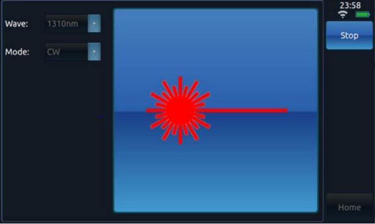
The final module present in most OTDRs is the VFL module. Once again, the name speaks for itself - this module allows you to use the OTDR as a Visual Fault Locator.
A VFL is typically used to physically see any faults present in a fiber optic cable, such as breaks and bends. It works by sending a visible pulse of light into the fiber cable- you can observe the light's behavior to ascertain whether there's a break or not. If there are any faults in the cable, the light will show at the location of that fault.
Visual Fault Locators are great pieces of testing equipment due to their simplicity and ease of use. In cases where you want to quickly identify faults in a shorter cable, the VFL module can act as a quick and easy way to do this. Unfortunately, however, the VFL module isn't the most thorough module when it comes to fiber optic testing. For instance, the range is typically very limited, allowing you to identify faults in only the shorter cables. Furthermore, in contrast to the OTDR module, which shows you a thorough and in-depth overview of the faults, the VFL module can only help you identify that there's a fault without telling you what type.
With that being said, having the VFL module is extremely valuable in cases where you want to quickly identify faults in shorter cables.
Conclusion
In conclusion, OTDRs stand as indispensable tools in the realm of fiber optic network testing. Their ability to precisely measure fiber optic cable characteristics, locate faults, and assess overall network health is critical in ensuring the efficiency and reliability of modern communication systems. Understanding how to use and interpret each module is of utmost importance, and will guarantee a successful troubleshooting experiences. As technology advances and the demand for high-speed data transmission grows, Jonard is dedicated to providing you with the optimal tools needed to thrive in the field, and our OTDR-1500 is no exception!
Comments
Login or Register to post comments.