How Do You Choose Fiber Optic Cable Connectors? We Can Help
How Do You Choose Fiber Optic Cable Connectors? We Can Help
The use of fiber optic cabling has been steadily growing since the late 70s and early 80s. Today fiber optic cabling is being used to replace copper cables in many regions. It’s this steady expansion of fiber cabling that is spurring the need for advancements in the fiber optic connector market.
This article will provide an introduction and brief overview of the most commonly used fiber optic connectors from descriptions, to common uses, to a few points to keep in mind when working with fiber optic cabling.
What are Fiber Optic Cable Connectors?
Fiber optic connectors are special pieces specifically designed to mechanically align and join, or terminate optical fibers, making it possible for two cables to be connected and disconnected quickly and safely. Unlike splicing, where two cable cores are permanently connected by fusion – heating the ends of two glass fiber cores to about 1,600 ֯ C and then joining them – the use of connectors gives a fiber technician the ability to easily test, maintain, and reconfigure networks.
The majority of fiber optic connectors are designed with ferrules that house and align the fibers for connection, allowing light to pass from one cable to the next, an active device, a tester, etc.
Fiber optic connectors are critically important for the reliability and performance of the network they are connected to. Basically, high-quality connectors will not lose much light because of reflections from a poor connection or misaligned fibers.
Components of Fiber Connectors
While hundreds of connectors have been introduced over the decades, only a small group of them are commonly used by fiber technicians.
Fiber optic cable connectors have several components, but the main three components are: the fiber ferrule, the connector housing, and the coupling mechanism.
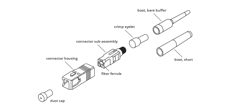
The ferrule is the piece that holds the glass fiber. The center is hollow and creates a firm grip on the fiber. Ferrules typically hold one strand of fiber and are made of ceramic, plastic, or metal. The connector housing or connector body is the largest component of a fiber optic connector. This is a plastic structure that holds the ferrule and attaches to the cable’s jacket and enables a technician to “mate” fiber optic cables. The coupling mechanism is the part of the connector body that holds the connector in place once attached to a device or cable. It is often a latching clip or a bayonet-style nut.
What are The Types of Fiber Optic Connectors?
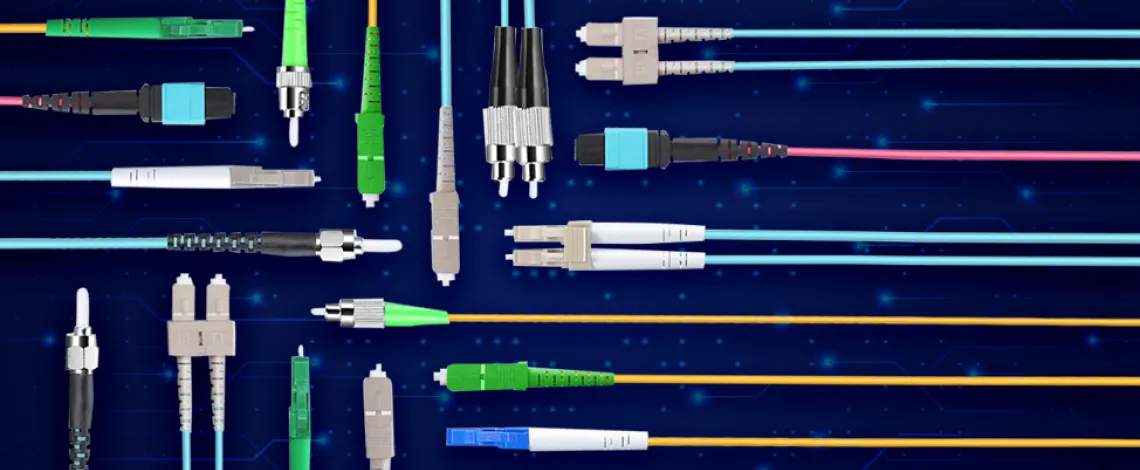
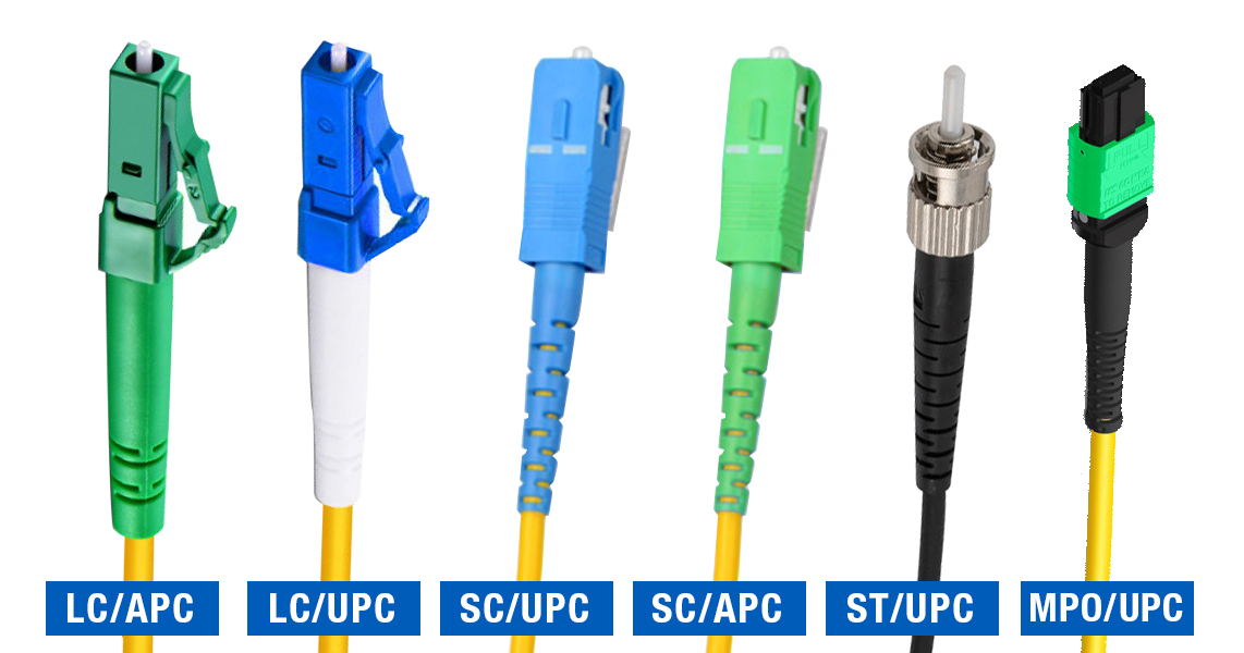
As mentioned, there have been hundreds of fiber connectors introduced to the market over the years. However, generally, the most common types technicians encounter are LC connectors, SC connectors, ST connectors, and MPO connectors.
Fiber Optic Polish Styles
Within the different connector styles, technicians need to be aware of the polish styles of the ferrules. The different polishes on the ferrules were created to increase the efficiency of light transmission at the connecting points and minimize the amount of back reflection. For this piece, we will only highlight APC polish and UPC polish.
What is the difference?
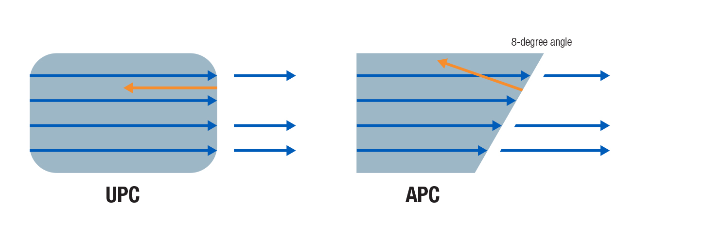
The angle on the ferrule end-faces. A UPC or Ultra Physical Contact style has a relatively flat end-face, whereas APC or Angled Physical Contact style has an end-face with an 8-degree angle. Any light that may be reflected back with UPC connectors will be reflected directly back to the light source, and the angled end-face on an APC connector can cause any light reflected back to be reflected into the cladding.
Another notable difference between the polish styles is their colors. UPC connectors are blue and APC connectors are green. And for obvious reasons, UPC and APC connectors can’t be used interchangeably.
LC Connectors
Known as the Lucent connector (AKA: little or local connectors) these are small form factor connectors that use a 1.25 mm ferrule. LC connectors feature a ceramic ferrule and have a latch mechanism. They are half the size of SC connectors, which makes them popular for datacoms and high-density racks, and patch panel applications.
SC Connectors
These connectors were some of the first to be introduced to the market after the invention of the ceramic ferrule. Referred as the “square connector,” the SC connector has a snap-in or a “push-pull” locking tab on the end, and a 2.5 mm ferrule. The SC connectors are known for their excellent performance, which is why they dominated fiber optics for more than a decade. Like the LC connectors, SC connectors can be joined with another connector by a plastic clip in a “duplex” configuration.
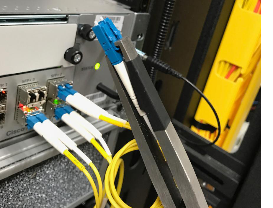
The narrow latch and snap-in mechanism featured in both LC and SC connectors inspired the creation of tools like our Fiber Connector Tool for LC, SC Connectors (FCT-200). These tools feature narrow, rubber-coated bent noses to reach and pull connectors from tightly packed spaces without damaging them.
ST Connectors
These connectors are known for their straight connector body and were some of the first connectors created for fiber optic cabling. These feature a 2.5 mm rounded ferrule and a plug and a socket combination that is secured by twisting the bayonet lock. One of the main features of the ST connectors is their ability to function for applications with both, small distances and systems that ask for larger distances.
ST connectors, however, must be plugged together carefully. Installers who may not be familiar with these may experience a significant amount of light loss because of improper installation. Despite the potential drawback, ST connectors are used far more often than SC connectors because of their versatility and flexibility. These connectors are great in small or tight spaces and bend as far as 90 degrees.
ST Connectors can provide almost unlimited bandwidth at high speeds over distances -both short and long when used with fiber patch cables. These cables are perfect for connections that take place in fiber patch panels, hubs, media converters, routers, and more.
MPO/MTP Connectors
These connectors are the biggest of the four types we’re focusing on. MPO is an acronym that stands for Multi-Fiber Push On. MTP is a brand name for an MPO connector manufactured by US Conec. These connectors can host up to 24 fibers and are generally used in high-density cabling environments such as data centers, industrial control applications, and broadcast communications.
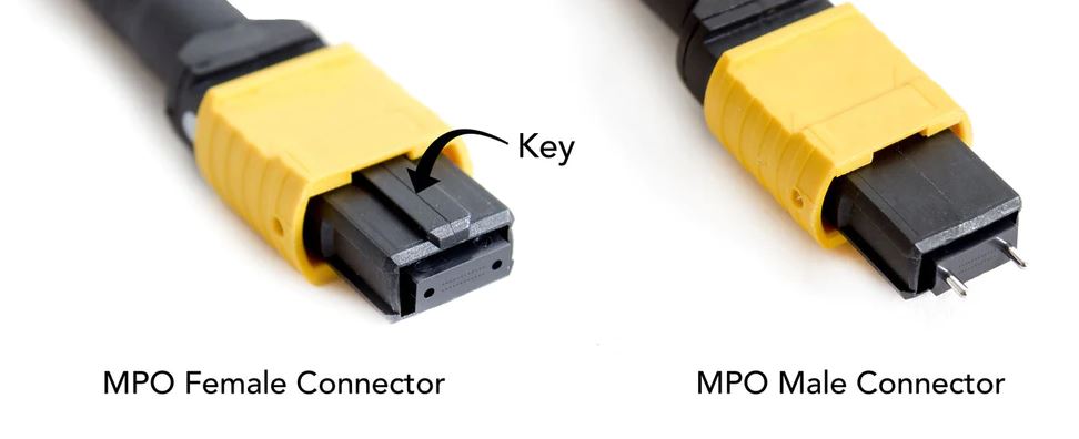
MPO connectors were the first generation of clip-clamping multi-core fiber connectors. MPO and MTP connectors look alike and are interchangeable. MTP and MPO connectors have a female type or a male type. Male connectors have two pins, while the female connector does not. Because MTP/MPO connectors can terminate multiple fibers, they greatly increase the cable density and help save space on racks.
While having many fibers at once can be beneficial for certain purposes, there are a few things to keep in mind. Unlike LC and SC connectors that have a single ferrule, MPO/MTP connectors are wide and contain multiple fibers. Meaning, an installer needs to keep track of each light signal and where it will be delivered. This is why there are several common polarity types that are used for these connectors: Type A, Type B, and Type C.
Type A, or the straight type, is where the key on the connector is up on one and underneath the other end. However, the fibers run straight across to the other side.
Type B, also known as the reversed type, is similar to the Type A polarity, except that the key is on the top side of both of the cables.
Type C is known as the flipped pairs type. This type of polarity swaps the pairs of each bundle of two. Meaning, the end of one side also has the key on the bottom side, similar to Type A.
How to Select the Right Fiber Optic Connector?
When selecting a connector, installers need to keep in mind that the connector style is determined by the equipment that the cabling will be plugged into, in addition to the type of fiber being used. There’s a big difference between singlemode and multimode fiber optic cabling.
Fiber connectors are designed specifically for the type of fiber being used. Singlemode fiber uses a 9/125 connector, which refers to the core and cladding diameter of the optical fiber.
Multimode fibers require either a 50/125 µm connector for OM2, OM3, and OM4 grades or a 62.5/125 µm connector for OM1 grade.
Conclusion:
Preparation and understanding of each type of fiber connector are critical.
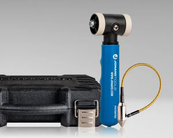
Preparation should also include a good understanding of proper cleaning practices when terminating fiber optic cabling. Special equipment including lint-free cleaning cloths, end cleaners, and fiber inspection microscopes, such as our Fiber Inspection Microscope (FIM-200), will help minimize attenuation.
Written by: Brenda Krulik, Project Coordinator, Jonard Tools
Comments
Login or Register to post comments.